
Radiasun is the leading manufacturer of cable and satellite meters in the world. Radiasun delivers the most satisfying products and services to the customers all over the world, with our own brands name, and also provides OEM and ODM for the most famous brands in the field.
AV6416-OTDR
AV6416 OTDR - 28/26/24dB high dynamic range(1310nm/1550nm/1490nm)
AV6416 OTDR Test Parameters
You can set preferences such as:
Mode:
Auto: Auto Mode. The OTDR will automatically set measurement condition, and scan the trace, then OTDR will automatically analyzes the trace and make the event table.
Real-Time: Manual Real-TIme mode. Set measurement condition(range, pulsewidth, att etc.) manually, then OTDR scan the trace real-time. Used to immediately view sudden changes in the fiber under test. In this mode, the trace SNR is lower than in average mode and the trace is not averaged, but refreshed, until you press START again or press ESC .
Average:Manual Average mode. Set measurement condition(range, pulsewidth, att etc.) manually, then OTDR scan the trace in average mode. Used to improve the trace SNR. In this mode, the detection of low-level events is enhanced and acquisitions are averaged for up to value of time(see following) or until you START again or press ESC.
Times:
The average counts of auto test or manual average mode. Generally, longer times generates cleaner traces(this is especially true with long- -distance traces), because, as the average count increases, more of the noise is averaged out. This averaging increases the signal-to-noise ratio and the OTDRdetect small events. The value of count is 10 to 100 in auto test mode. The value of count is 1 to 4000 in manual average mode.
Item:
Select item to measure splice loss, reflectance, and fiber section attenuation.
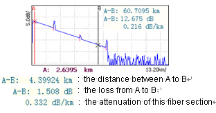
Loss:
To measure fiber section attenuation. After you set two markers
(marker A and marker B) on trace, the distance between marker A to marker
B. the loss from marker A to marker B and the attenuation of this fiber `
section will be displayed in the region of results. See the following figure.
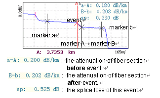
Splice: To measure splice loss of event. After you set four markers(marker a,
marker A, marker B and marker b) on trace, the attenuation of fiber section before event, the attenuation of fiber section after event and the splice loss of this event will be displayed in the region of results. See the following figure.
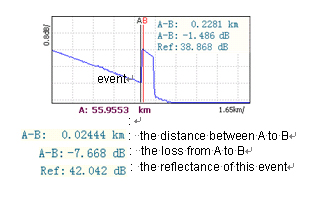
Reflect: To measure reflectance of event. After you set tow markers(marker A and marker B), the distance between marker A to marker B, the loss from marker A to marker B and the reflectance of this event will be displayed in region of results. See the following figure.
WL: (WaveLength)
To select the wavelength you want for testing.
Range:(km)
Used to set the length of the fiber span to be tested. The values of range are: 4km, 8km, 16km, 32km, 64km, 128km, 256km.
It should be increased to a value greater than the fiber length ( best twice than the fiber length).
Pulse: (ns)
Used to set the pulse width for the test. A longer pulse width travels further down the fiber, but results in less resolution. A shorter pulse width provides higher resolution, but less distance. The available distance ranges and pulse widths depend on your OTDR model. In addition, not all pulse widths are compatible or available with all distance ranges.
Att.: (dB)
Used to set attenuation of signal. If value of Att. is minimum, i.e. 0 dB, the distance span to be tested is maximal, but near the fiber is saturation. If value of Att. is maximal, i.e. 10 dB, the distance span to be tested is minimum, but can get smaller dead zone. The values of attenuation are 0dB, 5dB and 10 dB.
IOR: (index of refraction)
The index of refraction (IOR) (alse known as group index) is used to convert time-of-flight to distance. Having the proper IOR is crucial for all OTDR measurement associated with distance(event position, attenuation of fiber section, total length, etc). The IOR is a fiber characteristic that can be obtained through the cable or fiber manufacturer. It should be verified before each test. You can enter any IOR value between 1.0 and 2.0 inclusively.
Helix: (helix factor)
The helix factor takes into consiferation the difference between the length of cable and the length of the fiber inside the cable. It must be between 0.8 to 1.0. It can be obtained through the cable manufacturer.
Thresh. (dB): the threshold value of event
A fault is an optical event that passes a specified threshold. You can set the threshold of event.
After analyze the trace, Only events whose splice loss exceed the threshold of event will be listed in event table.
"Thank you for this great product I'm using it for 1 week and it is working like a charm.I am just trying to do the marketing here in my country and other nearby countries and will get back to you soon." Mauritius